

 QQ交谈
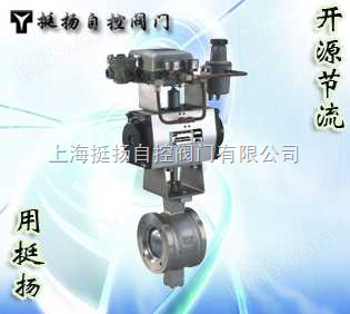
QQ交谈QJ(D/S)V、QJ(D/S)VY型精小型气动V型调节球阀
- 公司名称:
- 更新时间:
- 所 在 地:
- 生产地址:
- 浏览次数:
- 上海挺扬自控阀门有限公司
- 2015-09-22 20:34:18
- 上海市
- 1334
![]()
【简单介绍】
【详细说明】
一、概述Outline
QJ(D/S)V、QJ(D/S)VY型精小型气动V型调节球阀由气动活塞式执行机构和带V型切口的部分球面形的整体式球阀组成。属旋转类调节球阀。
气动V型调节球阀以压缩空气为动力源。接受控制系统来的4—20mA DC(0—10mA DC)讯号,通过电气转换或电—气阀门定位器将电信号转化成阀门动作所需要的气信号,对调节球阀进行调节。
气动V型调节球阀,其流道通畅,流量系数大,可调范围大,密封性能好。其带V型切口的阀芯,对阀座具有良好的剪切作用,使该产品适用于石油化工、造纸、污水处理及冶金等行业,对含有纤维和颗粒的悬浊液介质进行流量控制,特别适用于制浆、造纸生产过程中的纸浆、白水、黑液、白液等悬浮颗粒流体及浓浊状流体介质的自动调节。
气动活塞式执行结构可分为单作用和双作用两种。双作用使用在失电或失气时,阀门处于失电或失气时,阀门处于原始极限位置(全开或全闭),以确保生产过程处于安全位置。
QJ (D / S) V, QJ (D / S) VY fine small pneumatic V-type ball valve by the pneumatic piston actuator and with a V-notch portion of the overall spherical shape of ball valve components. Is a rotating type ball valve.
V-ball valve pneumatic compressed air as power source. Accept the control system to the 4-20mA DC (0-10mA DC) signal through the electrical conversion or electric - gas valve positioner to the valve movement into electrical signals needed gas signal, the ball valve to adjust.
Pneumatic V-ball valve, the flow smooth, flow coefficient, adjustable range, good sealing performance. The V-shaped incision with the spool of the valve seat has a good shearing, so that the product is suitable for petrochemical, paper, sewage treatment and metallurgical industries, containing fibers and particles in suspension media flow control , especially for pulp and paper production process of paper pulp, white water, black liquor, white liquor and other suspended particles in the fluid and the fluid medium Nongzhuo like the automatic adjustment.
Pneumatic piston implementation structure can be divided into single and double acting two. Dual role in the loss of power or loss of use of gas when the valve is out of power or loss of gas when the valve is in the original extreme position (open or closed) to ensure that the production process in a secure location.
二、主要技术参数和性能指标The main technical parameters and performance indicators
| 型 式 type | 直通式铸造球阀Through casting ball valve | ||||||||||||||
| 公称通径mm | 25 | 32 | 40 | 50 | 65 | 80 | 100 | 125 | 150 | 200 | 250 | 300 | 350 | 400 | |
| 公称直径mm | 20 | 26 | 33 | 40 | 53 | 66 | 86 | 104 | 128 | 170 | 212 | 255 | 300 | 340 | |
| 额定流量系数Kv | 25 | 36 | 63 | 100 | 160 | 250 | 400 | 600 | 950 | 1540 | 2500 | 3900 | 6150 | 980 | |
| 公称压力MPa | 1.6、6.4 | ||||||||||||||
| 气源压力Mpa | 0.4~0.6 | ||||||||||||||
| 连接形式 Connection form | 对夹式(管道法兰标准GB/T 9119-2000)、法兰式(JB/T82) Wafer (pipe flange standard GB / T 9119-2000), flange (JB/T82) | ||||||||||||||
| 介质温度℃ Temperature | 软密封-40℃~+180℃(KV V);硬密封-40℃~+450℃(KV Vy) Soft sealing -40 ℃ ~ +180 ℃ (KV V); seal -40 ℃ ~ +450 ℃ (KV Vy) | ||||||||||||||
| 额定行程 Rated travel | 90℃±3; | ||||||||||||||
| 固有流量特性 Inherent flow characteristic | 近似百分比Approximate percentage | ||||||||||||||
| 阀体材料 Body Material | 铸钢、铸不锈钢 Steel, cast stainless steel | ||||||||||||||
| 阀座材料Seat Material | 聚四氟乙烯、不锈钢、司钛莱硬合金 Teflon, stainless steel, titanium Levin hard alloy Division | ||||||||||||||
| 电气阀门定位器/电气转换器 Electropneumatic positioner / electrical converter | 输入信号Input signal | 4~20Ma DC或0~10Ma DC | |||||||||||||
| 防爆等级Explosion levels | 普通型、防爆型:隔爆型(EXdIIBT4)、本安型 Common type, explosion-proof: Flameproof (EXdIIBT4), intrinsically safe | ||||||||||||||
| 执行机构借口Actuator excuse | 1/8”G(GTX52、63、75、92) NAMUR1/4”G(GTX110、118、127、160、210、254、255) | ||||||||||||||
| 可调比Adjustable ratio | 300:1 | ||||||||||||||
注:DN25—250采用对夹式、DN300—400采用法兰式
Note: DN25-250 used for clip-on, DN300-400 using flange
三、性能指标Performance indicators
| 项 目 Item | 指标值Index value | 项目Item | 指标值Index value |
| 基本误差% Basic error% | ±2.0、±1.5 | 始终点偏差% Always point deviation% | ±2.5 |
| 回 差% Differential% | 2.0、1.5 | 允许泄漏量 1/hAllowable leakage 1 / h | 软密封:IEC534-4,VI级 Soft sealing: IEC534-4, VI ??level |
| 死 区% Dead% | 0.8、0.6 |
注:带定位器的指标值
Note: The index value with a locator
四、允许压差Permissible differential pressure
1、双作用执行机构(PN1. 6 4. 0阀体)Double-acting actuators (PN1. 6 4. 0 body)
公称通径mm | 25 | 32 | 40 | 50 | 65 | 80 | 100 | 125 | 150 | 200 | 250 | 300 | ||
| 执行结构 Executive Structure | 允许压差Permissible differential pressure | |||||||||||||
| AGT | 软密封 Soft sealing | 关闭 Close | 3.21 | 2.41 | 1.31 |
|
|
|
|
|
|
|
|
|
| △P | 0.74 | 0.52 | 0.31 |
|
|
|
|
|
|
|
|
| ||
| 硬密封 | 关闭 Close | 4.99 | 4.10 | 3.13 |
|
|
|
|
|
|
|
|
| |
| △P | 0.74 | 0.52 | 0.31 |
|
|
|
|
|
|
|
|
| ||
| AGT | 软密封 Soft sealing | 关闭 Close | 3.97 | 3.77 | 3.37 | 2.15 | 1.29 | 0.70 |
|
|
|
|
|
|
| △P | 1.72 | 1.27 | 0.83 | 0.53 | 0.30 | 0.16 |
|
|
|
|
|
| ||
| 硬密封 | 关闭 Close | 4.99 | 4.99 | 4.99 | 4.99 | 2.80 | 1.33 |
|
|
|
|
|
| |
| △P | 1.72 | 0.83 | 0.53 | 0.30 | 0.16 |
|
|
|
|
|
|
| ||
| AGT | 软密封 Soft sealing | 关闭 Close |
|
| 3.37 | 2.15 | 1.29 | 1.25 |
|
|
|
|
|
|
| △P |
|
| 1.33 | 0.87 | 0.49 | 0.28 |
|
|
|
|
|
| ||
| 硬密封 | 关闭 Close |
|
| 4.99 | 4.99 | 2.80 | 2.62 |
|
|
|
|
|
| |
| △P |
|
| 1.33 | 0.87 | 0.49 | 0.28 |
|
|
|
|
|
| ||
| AGT | 软密封 Soft sealing | 关 闭 Close |
|
|
|
|
| 2.05 | 0.70 |
|
|
|
|
|
| △P |
|
|
|
|
| 0.48 | 0.16 |
|
|
|
|
| ||
| 硬密封
| 关闭 Close |
|
|
|
|
| 4.52 | 1.56 |
|
|
|
|
| |
| △P |
|
|
|
|
| 0.48 | 0.16 |
|
|
|
|
| ||
| AGT | 软密封 Soft sealing | 关闭 Close |
|
|
|
|
| 2.05 | 2.03 | 1.15 | 0.68 |
|
|
|
| △P |
|
|
|
|
| 0.82 | 0.45 | 0.25 | 0.19 |
|
|
| ||
| 硬密封 | 关闭 Close |
|
|
|
|
| 4.52 | 4.50 | 2.31 | 1.43 |
|
|
| |
| △P |
|
|
|
|
| 0.82 | 0.45 | 0.25 | 0.19 |
|
|
| ||
| AGT | 软密封 Soft sealing | 关闭 Close |
|
|
|
|
|
| 2.03 | 2.54 | 1.54 | 0.68 |
|
|
| △P |
|
|
|
|
|
| 0.81 | 0.52 | 0.40 | 0.13 |
|
| ||
| 硬密封 | 关闭 Close |
|
|
|
|
|
| 4.50 | 4.97 | 3.23 | 1.13 |
|
| |
| △P |
|
|
|
|
|
| 0.81 | 0.52 | 0.40 | 0.13 |
|
| ||
| AGT | 软密封 Soft sealing | 关闭 Close |
|
|
|
|
|
|
| 2.54 | 1.54 | 1.52 | 0.84 | 0.62 |
| △P |
|
|
|
|
|
|
| 0.91 | 0.69 | 0.29 | 0.15 | 0.11 | ||
| 硬密封 | 关闭 Close |
|
|
|
|
|
|
| 4.97 | 3.23 | 2.68 | 1.47 | 1.11 | |
| △P |
|
|
|
|
|
|
| 0.91 | 0.69 | 0.29 | 0.15 | 0.11 | ||
| AGT | 软密封 Soft sealing | 关闭 Close |
|
|
|
|
|
|
|
|
| 2.11 | 1.82 | 1.31 |
| △P |
|
|
|
|
|
|
|
|
| 0.70 | 0.38 | 0.28 | ||
| 硬密封 | 关闭 Close |
|
|
|
|
|
|
|
|
| 3.72 | 3.25 | 2.52 | |
| △P |
|
|
|
|
|
|
|
|
| 0.70 | 0.38 | 0.28 |
注:1、表中数据为标准配置,可配用不同执行机构或改变填料材质改变允许压差;2、气源压力为0.4MPa(G)下
2、单作用执行结构(PN1. 6 4. 0 阀体)
| 公称通径mm | 25 | 32 | 40 | 50 | 65 | 80 | 100 | 125 | 150 | 200 | 250 | 300 | ||
| 执行结构 | 允许压差 | |||||||||||||
| AGT | 软密封 Soft sealing | 关闭 Close | 1.47 | 0.98 | 0.49 |
|
|
|
|
|
|
|
|
|
| △P | 0.34 | 0.23 | 0.12 |
|
|
|
|
|
|
|
|
| ||
| 硬密封 Seal | 关闭 Close | 4.29 | 2.60 | 0.90 |
|
|
|
|
|
|
|
|
| |
| △P | 0.34 | 0.23 | 0.12 |
|
|
|
|
|
|
|
|
| ||
| AGT | 软密封 Soft sealing | 关闭 Close
| 2.58 | 1.79 | 1.01 | 0.58 | 0.35 |
|
|
|
|
|
|
|
| △P | 0.60 | 0.53 | 0.45 | 0.16 | 0.08 |
|
|
|
|
|
|
| ||
| 硬密封 Seal | 关闭 Close | 4.99 | 3.66 | 2.33 | 1.13 | 0.35 |
|
|
|
|
|
|
| |
| △P | 0.60 | 0.42 | 0.24 | 0.16 | 0.08 |
|
|
|
|
|
|
| ||
| AGT | 软密封 Soft sealing | 关闭 Close | 3.97 | 3.00 | 2.03 | 1.27 | 0.76 | 0.33 |
|
|
|
|
|
|
| △P | 1.10 | 0.79 | 0.49 | 0.31 | 0.17 | 0.08 |
|
|
|
|
|
| ||
| 硬密封 Seal | 关闭 Close | 4.99 | 4.99 | 4.99 | 2.86 | 1.41 | 0.45 |
|
|
|
|
|
| |
| △P | 1.10 | 0.49 | 0.31 | 0.17 | 0.08 |
|
|
|
|
|
|
| ||
| AGT | 软密封 Soft sealing | 关闭 Close |
|
|
| 2.15 | 1.29 | 1.11 | 0.23 |
|
|
|
|
|
| △P |
|
|
| 0.79 | 0.44 | 0.25 | 0.06 |
|
|
|
|
| ||
| 硬密封 Seal | 关闭 Close |
|
| 4.99 | 4.99 | 2.80 | 2.31 | 0.51 |
|
|
|
|
| |
| △P |
|
| 1.21 | 0.79 | 0.44 | 0.25 | 0.06 |
|
|
|
|
| ||
| AGT | 软密封 Soft sealing | 关闭 Close |
|
|
|
|
| 2.05 | 0.88 | 0.43 | 0.21 |
|
|
|
| △P |
|
|
|
|
| 0.56 | 0.20 | 0.10 | 0.08 |
|
|
| ||
| 硬密封 Seal | 关闭 Close |
|
|
|
|
| 4.52 | 1.98 | 0.86 | 0.45 |
|
|
| |
| △P |
|
|
|
|
| 0.56 | 0.20 | 0.10 | 0.08 |
|
|
| ||
| AGT | 软密封 Soft sealing | 关闭 Close |
|
|
|
|
|
| 2.03 | 1.19 | 0.70 | 0.27 |
|
|
| △P |
|
|
|
|
|
| 0.46 | 0.25 | 0.19 | 0.05 |
|
| ||
| 硬密封 Seal | 关闭 Close |
|
|
|
|
|
| 4.50 | 2.35 | 1.45 | 0.39 |
|
| |
| △P |
|
|
|
|
|
| 0.46 | 0.25 | 0.19 | 0.05 |
|
| ||
| AGT | 软密封 Soft sealing | 关闭 Close |
|
|
|
|
|
|
| 2.54 | 0.54 | 0.98 | 0.52 | 0.52 |
| △P |
|
|
|
|
|
|
| 0.71 | 0.54 | 0.19 | 0.09 | 0.09 | ||
| 硬密封 Seal | 关闭 Close |
|
|
|
|
|
|
| 4.97 | 3.23 | 1.68 | 0.88 | 0.88 | |
| △P |
|
|
|
|
|
|
| 0.71 | 0.54 | 0.19 | 0.09 | 0.09 |
注:1、表中数据为标准配置,可配用不同执行机构或改变填料材质改变允许压差;2、气源压力为0.4MPa(G)下
Note: 1, data in the table for the standard configuration, the actuator can be equipped with different filler material change or change to allow pressure; 2, the supply pressure of 0.4MPa (G) under
五、执行机构转扭及动作时间Twist and turn actuators operating time
| 执行机构 | 63*90 | 75*90 | 83*90 | 92*90 | 110*90 | 118*90 | 127*90 | 160*90 | 210*90 | 254*90 | 255*90 | |
| 扭矩 | 400KPa | 23.2 | 40.0 | 56.0 | 77.6 | 112.8 | 168.0 | 220.0 | 440.0 | 948.0 | 1740.0 | 2172.0 |
| 500KPa | 29.0 | 50.0 | 70.0 | 97.0 | 141.0 | 210.0 | 275.0 | 550.0 | 1185.0 | 2715.0 | 2715.0 | |
| 动作时间(S) | 0.241 | 0.333 | 0.429 | 0.444 | 0.461 | 0.60 | 0.857 | 1.62 | 3.33 | 6.00 | 7.50 | |
注:双作用执行机构在75%负载情况下的动作时间
Note: The double-acting actuators under load at 75% operating time
六、可配附件Available Accessories
电-气阀门定位器、电-气转换器、空气过滤减压器、手轮机构等。
Electric - gas valve positioners, electric - gas converter, air filter regulator, hand wheel institutions.
七、外形尺寸及重量Dimensions and weight
QJSV-16型气动V型调节球阀QJSV-16 Pneumatic V-ball valve
| 公称通径 DN | 对夹 Wafer | 法兰 Flange | H1 | H2 | L1 | D1 | 重量Kg |
| L | L | ||||||
| 25 | 50 |
| 177 | 57 | 155 | 85 | 16 |
| 40 | 60 |
| 183 | 63 | 110 | 17 | |
| 50 | 75 | 108 | 203 | 92 | 203 | 125 | 19 |
| 65 | 85 | 145 | 210 | 100 | 145 | 21 | |
| 80 | 100 | 165 | 225 | 108 | 160 | 23 | |
| 100 | 115 | 195 | 233 | 117 | 290 | 180 | 27 |
| 125 | 135 | 210 | 280 | 140 | 210 | 38 | |
| 150 | 160 | 229 | 303 | 177 | 240 | 47 | |
| 200 | 200 | 292 | 335 | 200 | 368 | 295 | 75 |
| 250 | 245 | 330 | 379 | 252 | 355 | 107 | |
| 300 |
| 356 | 410 | 270 | 410 | 180 | |
| 350 |
| 400 | 430 | 320 | 450 | 470 | 260 |
| 400 |
| 420 | 480 | 390 | 525 | 360 |
相关产品
- PBQ340H双偏心半球阀
- Q661F锻造不锈钢对焊上装式球阀
- Q647F型双相不锈钢气动固定球阀
- Q671F意大利式超短型不锈钢气动对夹球阀
- Q641F气动(单,双作用)法兰不锈钢球阀
- Q671F调节型气动意大利式超短型,超薄型球阀
- 三段式气动球阀45°三段式气缸气动法兰不锈钢球阀
- ZJJQ三片式气动调节型内螺纹球阀
- Q611F型Q611F型气动三片式法兰球阀
- Q641FQ641F不锈钢气动日标,美标球阀
- QV677F气动V型调节球阀
- D73F46气动衬氟调节(切断)蝶阀
- Q614型气动三通内螺球阀
- 气动超薄球阀
- 气动卡箍式快装卫生球阀
- 气动三通法兰球阀
- QJRN型气动三片式内螺纹、焊接、卡箍、承插焊接球阀
- ANSI标准气动球阀
- 气动PVC球阀
- 气动对夹刀型闸阀
- 气动法兰连接闸阀
- Q641F气动V型 调节球阀
- ZSHO型ZSHO型气动O型切断球阀
- 气动三通 球阀
- Q641F46Q641F46型气动衬氟球阀
- 气动手轮调节球阀
- 气动二片式球阀
- 气动三片式球阀
- 气动换向球阀
- 气动卫生快装球阀
- 气动喷煤粉球阀
- 气动 塑料球阀
- 气动广式球阀
- QJ(D/S)RN型-16p-8精小型气动螺纹O型切断球阀
- QJ(D/S)R型精小型气动O型切断球阀
- QJ(D/S)RF型精小型气动衬氟O型切断球阀
- QJ(A/B/C)R型气动活塞两段切断球阀
- QJ(D/S)V、QJ(D/S)VY型精小型气动V型调节球阀
- QJ(D/S)RZ型气动高真空O型球阀
- Q647F型气动固定球阀
请输入产品关键字:

邮编:200070
联系人:朱经理
电话:021-63815180
传真:86-021-63815099
手机:13701838729
售后电话:021-63815180
留言:发送留言
网址:www.ty-v.com
商铺:https://www.bf35.com/st29511/